
Logic tells you a certain proposition is true if several conditions are true. Logic is applied in a digital circuit to implement logic functions. Circuits that performs logic operations specified are called logic gates.
There are three basic logic operations
- NOT
- AND
- OR
These are indicated by following shape symbols

The lines connected to the left side of each symbol are inputs and line on the right is output. In logic operations, the conditions mentioned earlier are represented by HIGH and LOW. Each of the logic operations produces a unique result for a given set of conditions.
NOT
The NOT operation inverts the logic level. When the input is HIGH the output will be LOW. When the input is LOW the output will be HIGH. Logic circuit inverter is used to implement NOT operation.

In Boolean algebra complement of a variable is represented by a bar over a digit. The two possible input-output combinations of an inverter(not gate) are,

This operation of an inverter(not gate) is summarized in the following table which shows the output for each possible inputs. This is called a truth table.
| INPUT (A) | OUTPUT (Ā) |
|---|---|
| LOW (0) | HIGH (1) |
| HIGH (1) | LOW (0) |
AND
An AND gate is composed of a single output and multiple inputs. The AND operation produces HIGH output only when all of its inputs are HIGH. When any or all inputs are LOW, then the output is LOW. The basic purpose of AND gate is to determine whether all conditions are simultaneously true.

In Boolean expression AND operation is represented either by placing a dot ( . ) between the variables or by writing the variables together. The four possible input-output combinations of a two-input AND gate are,

Operation of an AND gate is described in the truth table.
| INPUT (A) | INPUT (B) | OUTPUT (A.B) |
|---|---|---|
| LOW (0) | LOW (0) | LOW (0) |
| LOW (0) | HIGH (1) | LOW (0) |
| HIGH (1) | LOW (0) | LOW (0) |
| HIGH (1) | HIGH (1) | HIGH (1) |
OR
An OR gate is composed of a single output and multiple inputs. The OR operation produces HIGH output when any of its inputs are HIGH. The output is LOW only if both of the inputs are LOW.

The logical OR function is represented by placing a plus (+) in between the variables. The four possible input-output combinations of a two-input OR gate are,

The truth table of an OR gate is given below.
| INPUT (A) | INPUT (B) | OUTPUT (A+B) |
|---|---|---|
| LOW (0) | LOW (0) | LOW (0) |
| LOW (0) | HIGH (1) | HIGH (1) |
| HIGH (1) | LOW (0) | HIGH (1) |
| HIGH (1) | HIGH (1) | HIGH (1) |
XOR and X-NOR Gates
Exclusive-OR (XOR)
The XOR gate has only two inputs. The output of an XOR gate is only HIGH when the two inputs are at different logic levels. That is, if X is the output then X is HIGH when input A is HIGH and B is LOW or when input A is LOW and B is HIGH.
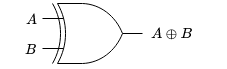
XOR operation is represented by a + symbol with a circle around it. The four possible input-output combinations of XOR gate is,

This operation can be summarized in the truth table.
| INPUT (A) | INPUT (B) | OUTPUT (A XOR B) |
|---|---|---|
| LOW (0) | LOW (0) | LOW (0) |
| LOW (0) | HIGH (1) | HIGH (1) |
| HIGH (1) | LOW (0) | HIGH (1) |
| HIGH (1) | HIGH (1) | LOW (0) |
Exclusive-NOR
Like XOR gate the XNOR gate also has only two inputs. The bubble on the right side of the XNOR symbol indicates that the output is opposite of XOR gate.

The output of an XNOR gate is only HIGH when the two inputs are at same logic levels. That is, if X is the output then X is HIGH when both A and B is HIGH or both A and B is LOW.

The operation is summarized in the truth table.
| INPUT (A) | INPUT (B) | OUTPUT (A XNOR B) |
|---|---|---|
| LOW (0) | LOW (0) | HIGH (1) |
| LOW (0) | HIGH (1) | LOW (0) |
| HIGH (1) | LOW (0) | LOW (0) |
| HIGH (1) | HIGH (1) | HIGH (1) |