
Looping in 8085
Looping is a programming technique that instructs the Microprocessor to repeat tasks. It is accomplished by changing the sequence of execution using jump instructions.
Loops can be classified into two groups:
- Continous Loops.
- Conditional Loops.
Continous Loops
A continuous loops repeats a task continuously. It is setup by using unconditional jump instruction. A program with a continuous loop will keep repeating tasks until the system is reset as shown in the flowchart.

Conditional Loops
A conditional loop repeat a task if some conditions are satisfied. They are setup by conditional jump instructions. These instructions check flags(Z, CY, P, S) and repeat the tasks based on the flag values. These loops include counting and indexing.
Conditional Loop and Counter
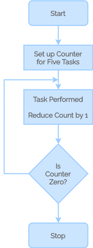
A counter is a typical application of the conditional loop. To achieve the looping task, the microprocessor requires a counter and a flag. A counter is set up by loading a suitable count into a register. Counting is accomplished by either incrementing or decrementing the counter. A conditional jump instruction creates the loop and the end of counting is indicated by a flag.
The following flowchart illustrates the approach needed for the microprocessor to repeat a task five times.
Indexing
Pointing objects with sequential numbers is called indexing. Data bytes are stored in memory locations and are referred to by their memory locations.
Delay Generation in 8085
The counting method described above has a significant downside in that it is performed at such a high speed that only the final count can be seen. So to notice the counting, there must be an appropriate time delay between counts.
Depending on the time delay required, a register is loaded with a number, and then the register is decremented until it reaches zero by setting up a loop with a conditional jump instruction. The delay is caused by the loop, which is determined by the system’s clock period.
The following methods are used for generating delays:
- Using NOP instructions.
- Using 8-bit register as counter.
- Using 16-bit register pair as counter.
Using NOP Instructions
One of the most common applications of the NOP instruction is in the generation of delays. The NOP instruction requires four clock pulses to fetch, decode, and execute. As a result, this form of NOP instruction can be used to induce a few milliseconds of time delay.
Time Delay Using One Register
The following program will demonstrate the time delay using 8-bit counter.
       MVI B, FFH
LOOP:  DCR B
       JNZ LOOP
       RET
The first instruction will be executed once, which will take 7 T-states. The DCR C instruction requires 4 T-states. This will be executed 255 (FF) times. The JNZ instruction takes 10 T-states when it jumps (It jumps 254 times), otherwise it will take 7 T-States. The RET instruction requires 10 T-States.
So we can use this technique with some other values in the place of FF, when we need some small delay.
Time Delay Using a Register Pair
Instead of an 8-bit counter, we can do the same task with a 16-bit register pair. More time delay can be generated using this method. For example:
       LXI B,FFFFH
LOOP:  DCX B
       MOV A,B
       ORA C
       JNZ LOOP
       RET
This method can be used to get more than 0.5 seconds delay.
MVI B, FFH LOOP: DCR B JNZ LOOP RETThank You 😀
Thank you <3