
Requirements analysis leads to the specification of software’s operating characteristics, the identification of software’s interface with other system elements, and the establishment of constraints that software must meet. Requirements analysis helps you elaborate on basic requirements generated through inception, elicitation, and negotiation requirements engineering tasks.
The action of requirements modelling produces one or more of the following types of models:
- Scenario-based models of requirements from the perspective of various system “actors” Scenario-based models of requirements from the perspective of various system “actors” .
- Data models that depict the problem’s information domain.
- Class-oriented models that represent object-oriented classes (attributes and operations) and how classes collaborate to achieve system requirements.
- Flow-oriented models that represent the system’s functional elements and how they hey transform data as it moves through the system.
- Behavioral models that describe how software behaves in response to external “events” that describe how software behaves in response to external “events”
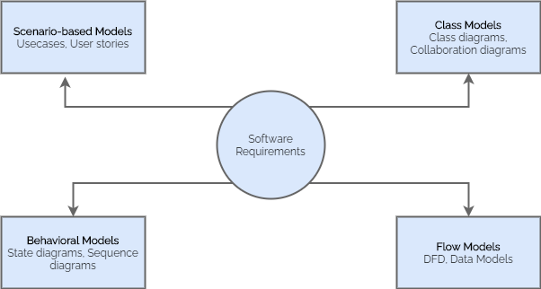
These models provide information to a software designer that can be turned into architectural, interface, and component-level designs.
Overall Objectives and Philosophy
Throughout the requirements modelling process, your primary focus should be on what, not how.
The requirements model must accomplish three basic goals:
- Describing what the client requires.
- Establishing a foundation for the production of a software design.
- Defining a set of criteria that can be validated once the software is constructed.
The analysis model bridges the gap between a system-level description of the overall system or business functioning as it is delivered through the use of software, hardware, data, human, and other system aspects and a software design. This relationship is shown in the figure below.

Analysis Rules of Thumb
Arlow and Neustadt suggest a few useful rules of thumb to follow when developing the analytical model.
- The model should concentrate on requirements that are obvious within the problem or business domain. The level of abstraction should be moderate. “Don’t get bogged down in details” that attempt to explain how the system will function.
- Each element of the requirements model should contribute to a broader understanding of software needs and provide insight into the system’s information domain, function, and behaviour.
- Put off thinking about infrastructure and other nonfunctional models until design. That is, while a database may be required, the classes required to implement it, the functions required to access it, and the behaviour that will be displayed as it is used should be considered only after the problem domain analysis is complete.
- Keep coupling to a minimum across the system. Relationships between classes and functions must be represented. If the level of “interconnectedness” is excessively high, however, efforts should be made to reduce it.
- Check to see if the requirements model gives value to all stakeholders. Each constituency has a different application for the model. Business stakeholders, for example, should use the model to validate requirements; designers should use the model as a foundation for design; and QA personnel should use the model to help prepare acceptance tests.
- Keep the model as simple as possible. Don’t make any new diagrams if they don’t contribute any new information. When a basic list will enough, avoid using complex notational forms.
Requirement Modelling Approaches
Structured Analysis
Structured analysis is one approach to requirements modelling that treats data and the processes that transform it as separate entities. Data objects are modelled in such a way that their attributes and relationships are defined. Processes that change data items are designed in such a way that it is clear how they transform data as it flows through the system.
Object-Oriented Analysis
The object-oriented analysis focuses on the definition of classes and how they interact with one another. The Unified Process and UML are both mostly object-oriented.
Requirements Modelling Strategies
Your understanding of software requirements grows in direct proportion to the number of different dimensions of requirements modelling. Although you may not have the time, resources, or motivation to create every representation, remember that each modelling technique provides a unique perspective on the problem. As a result, you’ll be able to evaluate whether you’ve properly specified what has to be done.
Flow-Oriented Modelling (The Data Flow Diagram)
The DFD analyzes a system from the viewpoint of input-process-output. In other words, data objects enter the software, are modified by processing elements, and then exit the software. Data objects are represented as labelled arrows, whereas transformations are represented as circles (also called bubbles). The DFD is displayed in a hierarchical format. That is, the first data flow model (also known as a level 0 DFD or context diagram) reflects the entire system. Subsequent data flow diagrams refine the context diagram, adding more detail with each level.
You can use the data flow diagram to create models of the information domain and the functional domain. As the DFD is refined into higher levels of detail, an implicit functional decomposition of the system is performed.
Guidelines of a Data Flow Diagram
- The software/system should be represented as a single bubble in the level 0 data flow diagram.
- Primary input and output should be carefully noted.
- Refinement should begin by isolating candidate processes, data objects, and data stores to be represented at the next level.
- All arrows and bubbles should be labelled with meaningful names.
- Information flow continuity must be maintained from level to level.
- Each bubble should be refined one at a time. The data flow diagram has a natural tendency to become overly complicated. This happens when you try to convey too much detail too soon, or when you describe procedural features of the product instead of information flow.
For certain applications, the data model and data flow diagram are all that is required to gain meaningful insight into software requirements. A substantial class of applications, on the other hand, are “driven” by events rather than data, generate control information rather than reports or displays, and process information with a strong emphasis on speed and performance. For such applications, Control flow modelling is required, in addition to data flow modelling.
Behavioral Model
The system’s behaviour can be represented as a function of certain events and time. The behavioural model describes how the software will respond to outside events or stimuli. Go through the following steps, to make the model.
- Evaluate all use cases to properly understand the system’s interaction sequence.
- Recognize the events that drive the interaction sequence and understand how these events are related to specific objects.
- For each use case, create a sequence.
- Create a system state diagram.
- Go over the behavioural model again to ensure its accuracy and consistency.