
A potentiometer is a device where a resistive wire is wound on an insulating core provided with a sliding contact. It can be excited with a DC or AC voltage source. The slider movement can be translational (straight) rotational or a combination of both.
Schematic diagram of a resistive potentiometer is shown in figure.
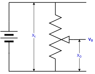
Here, Xt is the total length between two endpoints and the resistance between these two endpoints are always constant. The resistance between sliding point and endpoint will change with respect to the input displacement X0.
If V is the excitation voltage, then the output voltage V0 can be expressed as

If the total resistance is Rt and the resistance between sliding point and the endpoint is R0 then by voltage dividing rule V0 can be expressed as

It is clear that the output voltage in the potentiometer is proportional to the displacement.
Loading effect on Potentiometer
The output of a potentiometer is generally connected to an amplifier or a meter(measuring device). The input impedance of this connected device acts as a load of the potentiometer and it will affect the current between the sliding contact and the end terminal. This situation is called the loading effect on a potentiometer.

If the input resistance of the connected meter is Rm, and the resistance between sliding point and the endpoint is R0 then the total effective resistance is given by

The effective voltage after connecting the load is

The error occured by connecting the load is
